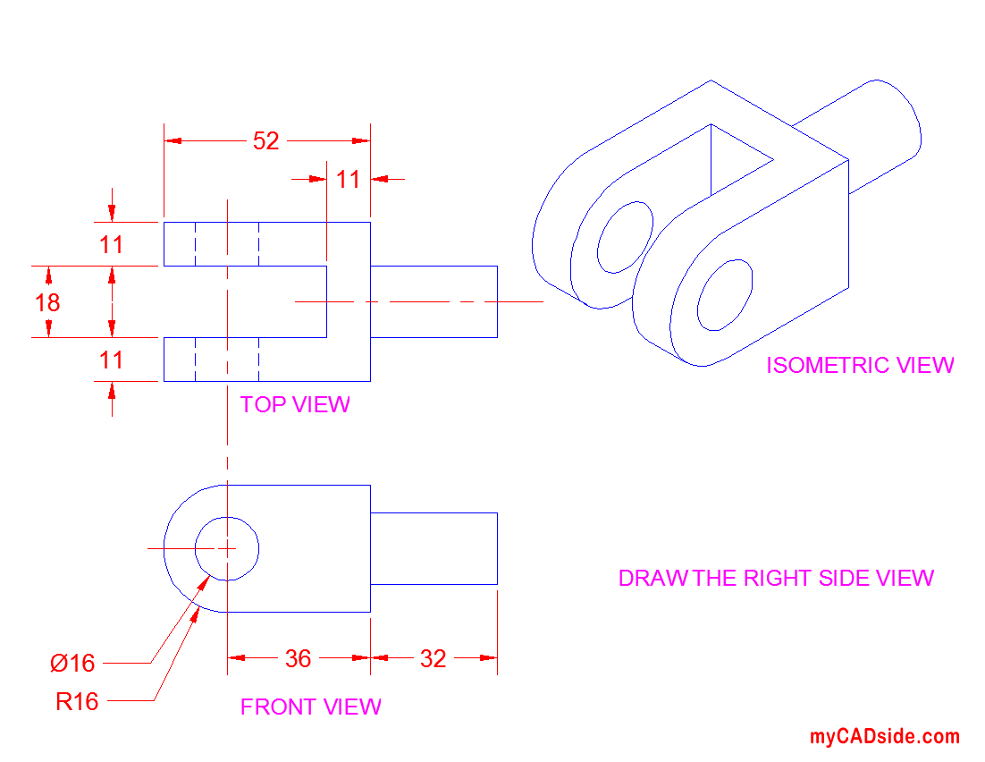
Autocad Orthographic View
If you play more than two games on a regular basis, the Anker 8200 adds an extra level of annoyance. This process is cumbersome and prone to errors, since the mouse will automatically reset to defaults when you move it between computers.For comparison purposes, most comparable Logitech and Razer mice (and even the Anker 5000) can hold at least five simultaneous profiles.If you want to take your profiles with you, you'll need to transfer the files manually and load them up every time you want to switch a game. Anker 8000 dpi driver download.
For an overview, see Orthos (Part 1)
Autodesk 3DS Max 2015. 3D Studio Max is supper fast and latest version designing software in the world. This version is very simple for new user uses by their project create. It is not only for new user it is for professional designer. Autodesk 3ds Max 2015 17.1 is available as a free download on our software library. 3dsmax.exe is the most frequent filename for this program's installer. The most popular versions of the tool are 17.1 and 17.0. The program relates to Photo & Graphics Tools. This software is an intellectual property of Autodesk. 
- Definition Of Orthographic View
- Autocad Orthographic View Tut
- Autocad Orthographic View Images
- Autocad Orthographic Drawing
- Autocad Orthographic View Vs
Definition Of Orthographic View
- On the ribbon, click Home tab Ortho Views panel Create Ortho View. Note: Alternatively, you can click the Orthographic DWG tab in the Project Manager, open an orthographic drawing, and, on the ribbon, click New View.
- In the Select orthographic Drawing, do one of the following and click OK:
- Under Orthographic Drawings In the Project, click an existing drawing.
- Click Create New. In the New DWG dialog box, in the File Name box, enter a name. Enter an author name. Click OK.
- In the drawing, click the OrthoCube. You can use the grips to move and resize the cube, or you can use AutoCAD to move, rotate, and align precisely. The highlighted (red) panel indicates the current view, for example, top. Note: Click a corner of the ViewCube, if necessary, to access the grips you want on the OrthoCube.
- On the ribbon, Ortho Editor tab, do the following:
- On the OrthoCube panel, in the drop-down list, click a view (for example: Front). Note:
By default, the temporary drawing that is displayed is set to zoom in on all elements currently in the drawing. The ViewCube is set to Top view using WCS (world coordinate system). Click the corners of the ViewCube to find an angle that lets you work with OrthoCube grips easily.
- On the Output Size panel, in the Scale drop-down list, click a scale (for example: 1:16). You can also adjust the scale when you place the ortho drawing.
- (Optional) On the Output Size panel, click Paper Check to make sure the scale you've chosen is appropriate.
- (Optional) On the Library panel, click Save OrthoCube. In the Save View dialog box, enter a view name and click OK.
- On the Create panel, click OK.
- On the OrthoCube panel, in the drop-down list, click a view (for example: Front).
- In the orthographic drawing space, specify the position of the lower-left corner of the viewport. Note:
At the Command prompt, you can also specify the exact coordinates for the drawing. You can also specify the scale of the viewport before placing the viewport in the drawing by clicking ? to open the Select Ortho View Scale dialog box.
You can now annotate the orthographic drawing.

Autocad Orthographic View Tut
Autocad Orthographic View Images
- Different views in orthographic projections. The orthographic views should represent the true size and true shape of an object (as much as possible). Suggestions: Select the front view 1. The longest dimension of an object should be presented as a width (in a front view).
- Isometric drawing in AutoCAD 2014 and older versions: At first, you need to change your snap settings to isometric. Type DS on the command line and press enter. Drafting settings window will pop up from this window select snap and grid tab and make sure Isometric snap radio button is checked. Click OK to exit drafting settings window.
- This AutoCAD 2017 tutorial video demonstrates how to produce orthographic drawings. This AutoCAD 2017 tutorial video demonstrates how to produce orthographic drawings. MAKING PERSPECTIVE VIEWS.
Autocad Orthographic Drawing

Autocad Orthographic View Vs
My first layout is for five orthographic views. The front and two side elevations are correctly displayed as well as the top or plan view but the bottom view is incorrect. I used the View menu 3D View options. It would require a rotation of 180 degrees in the XY plane to be a geometrically correct bottom view. Orthographic Views 5-1 Introduction This chapter introduces orthographic views. Orthographic views are two-dimensional views of three-dimensional objects. Orthographic views are created by projecting a view of an object - Selection from Engineering Graphics with AutoCAD® 2015 Book. For an overview, see Orthos (Part 1) On the ribbon, click Home tab Ortho Views panel Create Ortho View. Note: Alternatively, you can click the Orthographic DWG tab in the Project Manager, open an orthographic drawing, and, on the ribbon, click New View. In the Select orthographic Drawing, do one of the following and click OK: Under Orthographic Drawings In the Project, click an existing drawing.